🔹Hall Effect Sensor Control
🔹Back-EMF Sensorless Control
🔹PID Speed Control with Potentiometer
🔹Constant Speed/ Constant Current PID
Brushless vs Brushed DC Motor [1]
BLDC (Brushless DC) motors eliminate the need for mechanical brushes by using electronic commutation. Instead of sending current through rotating windings, the coils are fixed on the stator, while the rotor carries permanent magnets. This offers lower maintenance and greater efficiency.

In contrast, brushed DC motors place the windings on the rotor and the magnets on the stator.

Six-Step Commutation [1]
A BLDC motor consists of a stator with three 120°-separated windings (phases A, B, and C) and a rotor with a single pole pair of permanent magnets.
Once an AC current is applied to the stator windings, two of three phases are energized, so a rotating magnetic field is generated.
The rotor, which contains permanent magnets, will start to rotate in an attempt to align itself with the stator’s magnetic field.
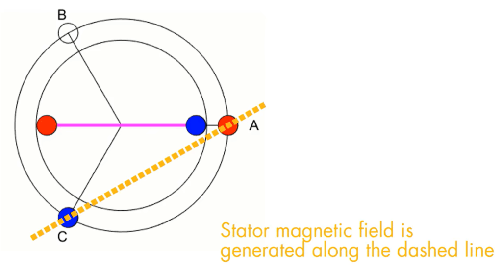
For a motor with one pole-pair, the stator’s magnetic field is shifted every 60 electrical degrees.

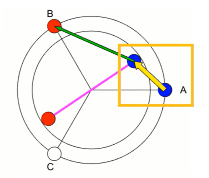
How the Stator and Rotor Interact
The arrow represents magnetic force, and its thickness indicates magnetic field strength.
The stator generates a magnetic field, and the rotor — containing permanent magnets — reacts when opposite poles attract, like poles repel. Therefore the rotor keeps rotating counterclockwise.
Once the rotor moves 60 electrical degrees, the stator switches phase to create a new magnetic field direction. This keeps the rotor chasing the field.

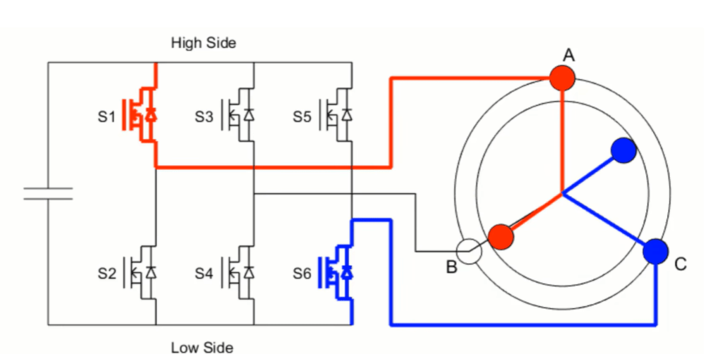
3-Phase Inverter Control [1]
A three-phase inverter is used to convert DC power into three-phase AC waveforms that energize the stator coils. It consists of six MOSFET switches (S1-S6):
- High-side switch ON: positive current to the phase
- Low-side switch ON: negative current from the phase
By turning ON a high-side and a low-side switch (e.g., S1 and S6), current flows from phase A to phase C, generating a magnetic field.
Hall Effect Sensor Mode
Hall sensors embedded in motor give the rotor position directly as a digital code, and the controller uses this code to decide which MOSFET pair should be turned on.
Sensorless Back-EMF Mode
In sensorless BLDC control, the rotor position is estimated from the back electromotive force (Back-EMF) induced in the motor windings. At any instant, two motor phases are driven (one high, one low), and the third phase is left floating.
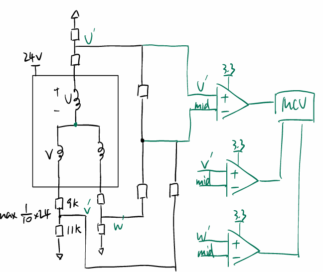
- The floating phase (U as example) voltage Vu′ can be expressed as: Vu′ =Vmid + Vind (Vind=Vemf)
- When the rotor moves, the back-EMF alternates polarity:
- Vind < 0 ⇒ Vu′< Vmid → falling edge.
- Vind > 0 ⇒ Vu′> Vmid→ rising edge.
- A comparator compares the floating phase to the virtual neutral point (mid-point).
- The zero-crossing point (when Back-EMF = 0) occurs exactly halfway between two commutation events. At the zero-crossing, the back-EMF transitions from positive to negative (or vice versa) depending on whether the N or S pole of the rotor is entering the coil.

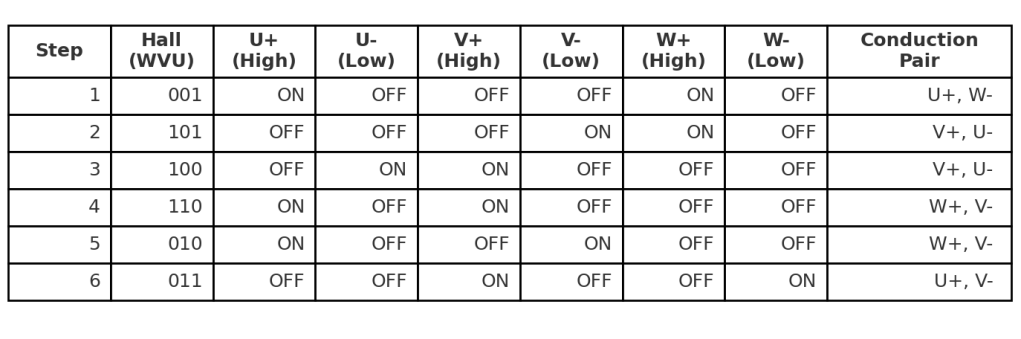
The sequence 001 → 101 → … is advanced every time a zero-crossing is detected, achieving six-step commutation.
Example: Six-Step Commutation with Back-EMF Detection
- Step 1: Phase C → +24 V, Phase A → 0 V, Phase B floating.
- Back-EMF of Phase B is monitored.
- When Phase B crosses zero (from negative to positive), commutate to the next step.
- Step 2: Phase B → +24 V, Phase A → 0 V, Phase C floating.
- Back-EMF of Phase C is monitored.
- When Phase C crosses zero, commutate to the next step.
- Step 3: Phase B → +24 V, Phase C → 0 V, Phase A floating.
- Back-EMF of Phase A is monitored.
- When Phase A crosses zero, commutate to the next step…
This table defines which high-side and low-side MOSFETs conduct at each commutation step after testing.
Hall Effect Sensor

The Hall sensor detects magnetic field strength and converts it into a digital signal.
When the magnetic field > BOPS, MOS ON, output switches low; when B < BRPS, the output returns high [2].
Main Power Stage
Bootstrap Capacitor
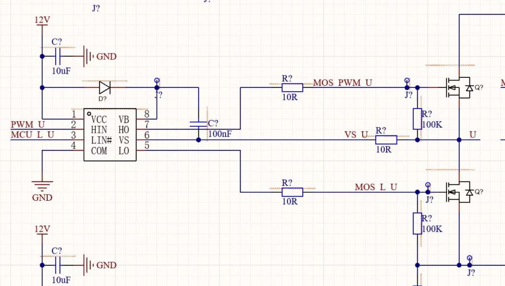
1. When the low-side MOSFET is ON
- The switching node (VS) is pulled down to 0 V.
- The bootstrap diode conducts, charging the capacitor from VCC (≈12 V).
- The capacitor stores about 12 V across its terminals.
2. When the high-side MOSFET turns ON
- The driver shifts the bootstrap capacitor upward so that the VB pin is approximately VS + 12 V.
- This provides a gate-to-source voltage (Vgs) of 10–12 V, fully enhancing the high-side MOSFET.
3. While the high-side MOSFET remains ON
- The bootstrap capacitor supplies the required gate charge to maintain Vgs.
- The capacitor will be recharged during the next cycle when the low-side MOSFET conducts again.
Three-Phase Bridge

- High-side MOSFETs are driven with PWM for voltage modulation.
- Low-side MOSFETs are controlled by GPIO on/off signals to minimize switching losses.
MOSFET Selection – NCE6020AK
- Voltage Rating
- The supply voltage is 24 V, so the MOSFET must withstand at least 35 V drain–source voltage (Vds).
- NCE6020AK provides 60 V Vds rating, giving sufficient margin.
- Current Rating
- The motor operates at 100 W / 24 V ≈ 4.1 A nominal, with phase currents up to 30–45 A during commutation or startup.
- NCE6020AK is rated for >60 A (pulsed), which is adequate.
- Conduction Loss
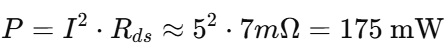
- With Rds(on) ≈ 7 mΩ [3], conduction loss at 5 A is acceptable
- Switching Performance
- The PWM switches at 30 kHz (T = 33 µs). With a minimum duty ratio of 10%, the MOSFET on-time is about 3 µs. To reduce switching losses, the requirement is Tr < Ton/10 ≈ 300 ns. For the NCE6020AK (Ciss ≈ 973pF) [3], assuming a driver equivalent output capacitance of 1 nF, the rise time is enough, estimated as

- Thermal Considerations
- Estimated power dissipation: ~175 mW conduction + switching losses.
- With Rθja ≈ 50 °C/W, junction temperature rise ≈ 175 mW × 50 = 9 °C, keeping MOSFET below 50 °C at room temperature.
Current Sensing
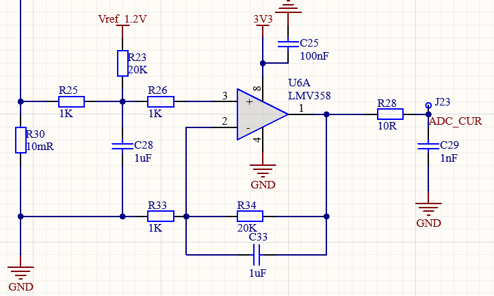
A 10 mΩ shunt resistor, amplified by a gain of 21× and shifted with a 1.2 V offset, converts the 0.1–5 A motor current into a magnified signal of 1.22–2.25 V, well within ADC’s 0–3.3 V input range.
PID Control Principle
The motor control loop is implemented using a PID (Proportional–Integral–Derivative) controller. The PID algorithm computes the control signal u(t)from the error e(t), which is the difference between the target reference yd (desired speed or current) and the actual feedback y(t):

The control output is [4]:

Proportional term (Kpe(t)): Provides immediate correction proportional to the error. A larger Kp increases response speed.
Integral term (Ki∫e(t)dt): Accumulates past error to correct long-term drift,
Derivative term (Kdde/dt): Fine-tunes response and damps overshoot.
Constant Speed Control
- Reference (target): Speed (rpm), set by ADC input (potentiometer).
- Feedback: Actual speed, measured by Hall sensors/Comparator.
- Error: Difference between target rpm and measured rpm.
- Control Action: PID adjusts PWM duty cycle to keep the motor speed constant, compensating for changes in load torque.
This loop ensures speed stability: when load increases, error grows, PID increases PWM duty to provide more current.
Constant Current Control
- Reference (target): Current (A), set by ADC input.
- Feedback: Actual current, measured by the shunt resistor + amplifier.
- Error: Difference between target and actual current.
- Control Action: PID updates PWM duty cycle to regulate phase current.
This mode ensures torque stability: the motor produces a nearly constant torque even if mechanical load or speed varies.
Testing Result
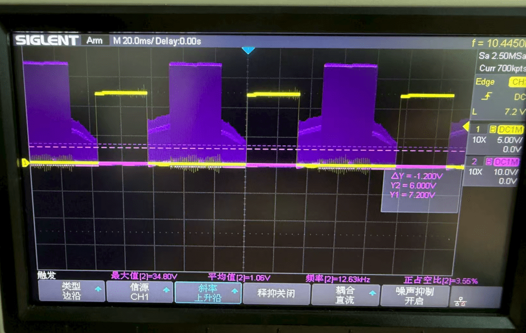
Yellow: MOSFET gate PWM drive signal.
Purple: Motor floating-phase voltage, which shows the PWM pattern superimposed with the back-EMF.
When a phase is floating, the rising portion of the purple waveform corresponds to the positive half-cycle of the back-EMF. During the active PWM interval, the phase voltage rapidly switches between high and low states due to MOSFET commutation. Near the end of the PWM cycle, a negative back-EMF appears as the motor transitions into the next commutation sector.
Reference
[1] MATLAB, “An Introduction to Brushless DC Motors | Brushless Motor Control with Simulink, Part 1”, YouTube, Feb. 6, 2019. [Online Video]. Available: https://www.youtube.com/watch?v=gNpoTPzEkco
[2] Unisonic Technologies Co., Ltd., UHE4913 Low Power Hall Effect Switch Datasheet, QW-R502-608.D, 2019. [Online]. Available: https://www.unisonic.com.tw/datasheet/UHE4913.pdf
[3] Wuxi NCE Power Co., Ltd., NCE6020AK N-Channel Enhancement Mode Power MOSFET Datasheet, v3.0. [Online]. Available: https://www.lcsc.com/datasheet/C108639.pdf
[4] University of Michigan, Control Tutorials for MATLAB and Simulink – Introduction: PID Control, Accessed: Aug. 21, 2025. [Online]. Available: https://ctms.engin.umich.edu/CTMS/index.php?example=Introduction§ion=ControlPID
