
🔹Input Voltage: 30V
🔹Output Voltage: ~5.04 V
🔹Transformer Turn Ratio: 3:1:2.4
🔹Oscillator Switching Frequency: ~253kHz
In current-mode control, duty cycles above 50% can cause subharmonic oscillation. The UC3844/45 avoid this by clamping duty cycle to 50%, but I chose the UC3842, which supports nearly 100% [1]. With external slope compensation added, my design achieves both stability and flexibility.
Design Overview
UC3842 integrates most of the building blocks (error amplifier, oscillator, PWM comparator, current sense) that I previously implemented discretely.
Discrete Flyback
July, 2025
UC3842 Boost Control Principle (5V → 10V)
As an example, I implemented a boost converter using the UC3842, with reference to UCx84x datasheet [1], shown in the diagram below.

- Startup (Vout < Target 10V)
- The error amplifier (E/A) output is high, driving the COMP pin voltage up (Black).
- This allows the PWM latch to open MOSFET at the start of each cycle.
- When the MOSFET turns on, the inductor current (Isense) ramps up.
- Current Sense Control (Cycle-by-Cycle Limiting)
- The rising Isense voltage (across Rsense) is continuously compared to the error amplifier output (Vfb).
- When Isense ≥ Vfb, the PWM comparator resets the latch, turning the MOSFET off (Red).
- The inductor current then discharges into the output, charging the capacitor and raising Vout.
- Oscillator Timing (Cycle Synchronization)
- The oscillator injects a short reset pulse each cycle to guarantee the MOSFET turns off periodically (Green).
- This prevents the MOSFET from staying on indefinitely.
- Approaching the Target Voltage (10V)
- As Vout increases, the FB voltage rises, reducing the E/A output.
- This causes the PWM comparator to trip earlier in the cycle, shortening MOSFET on-time.
- Less energy is delivered per cycle, and Vout stabilizes near the setpoint.
- Steady-State Regulation
- If Vout drops, FB decreases, E/A output rises → MOSFET duty cycle increases → Vout recovers.
- If Vout rises, FB increases, E/A output lowers → MOSFET duty cycle decreases → Vout falls back.
- This closed-loop process maintains a regulated 10V output.
Overcurrent [1]
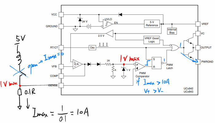
The UC3842 monitors the voltage across the sense resistor (Isense), which is proportional to the MOSFET current. When Isense exceeds the threshold (≈1 V), the PWM comparator trips and immediately turns off the MOSFET
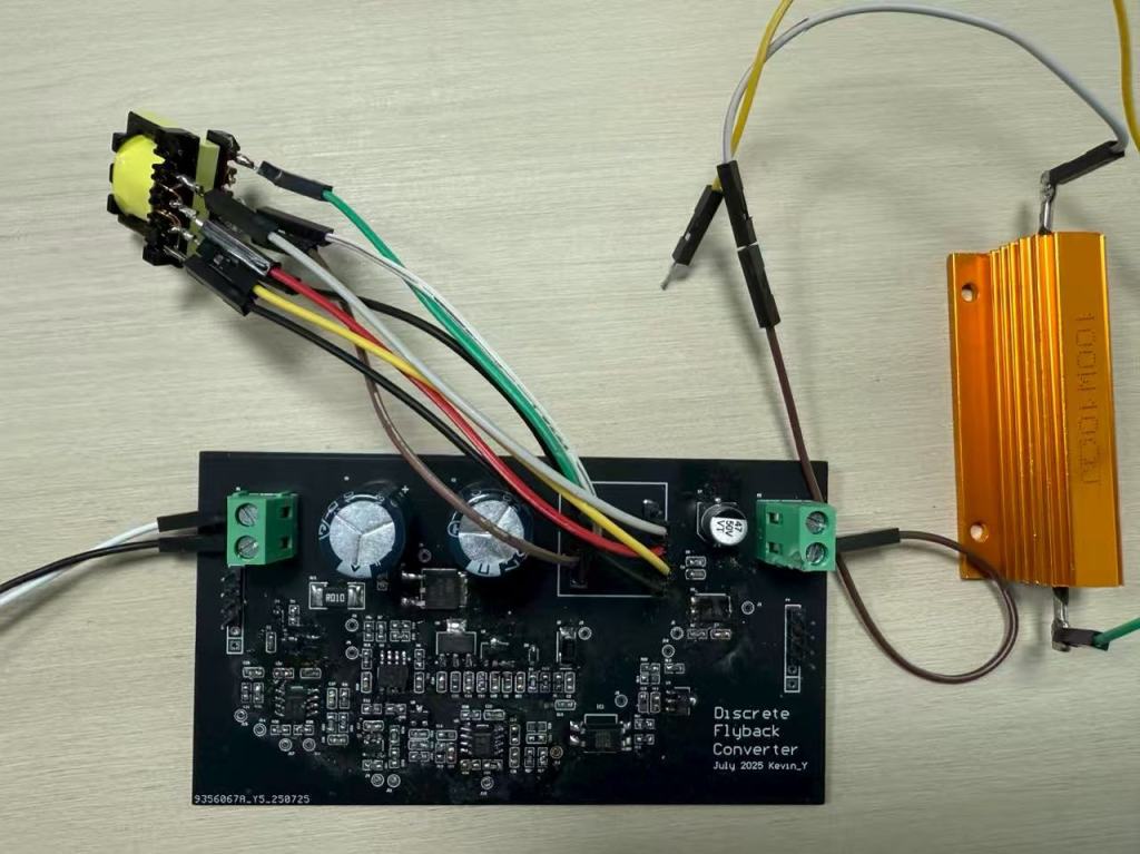
Schematics
Following the typical application circuit provided in the UCx84x datasheet, I was able to quickly complete the schematic design.


Challenges & Solutions
Startup supply issue
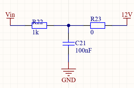
Initially, the source supply exhibited large ripple and unstable startup. The series resistor (1 kΩ) limited the current too much, causing a large voltage drop when the transformer was not yet supplying auxiliary power. As a result, the supply would turn on briefly, then shut down repeatedly.
Fix: Reduced the series resistance, ensuring sufficient startup current while still providing protection. This stabilized the VCC rail during startup.
Feedback Not Rising

The feedback pin (FB) remained stuck near 0 V, preventing proper regulation and keeping the duty cycle high. The root cause was traced to the RC snubber across the primary MOSFET: with an oversized capacitor, excessive energy was absorbed in the snubber instead of being delivered to the secondary.

Fix: By removing the snubber capacitor, the output voltage was able to rise, and the feedback loop began regulating normally.
Slow Output Ramp
When testing, the output voltage increased only after a long delay — the PWM required many cycles to push Vout up. This indicated that the current loop bandwidth was too low, slowing the response.
Fix: I increase the current loop bandwidth by adding resistors on outer voltage control loop, which allowed the converter to ramp up output much faster.
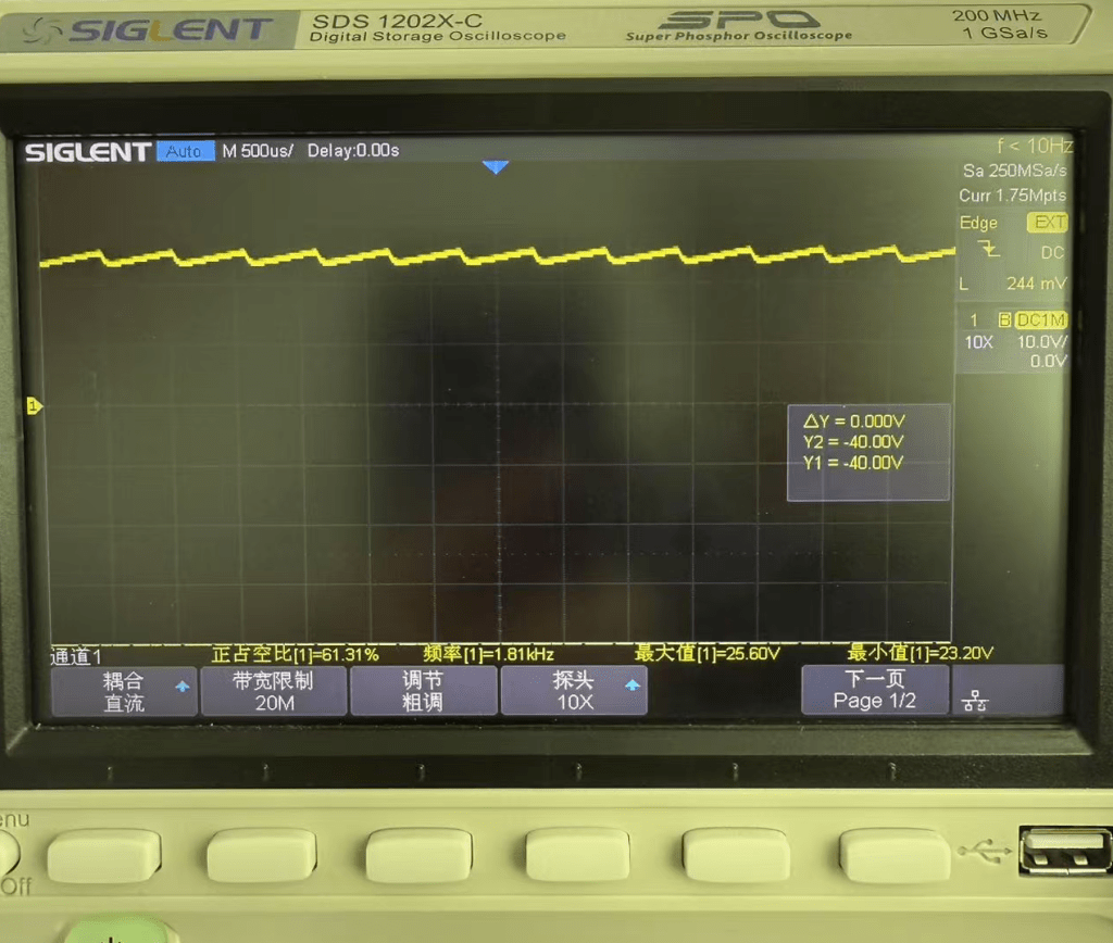
Testing Result
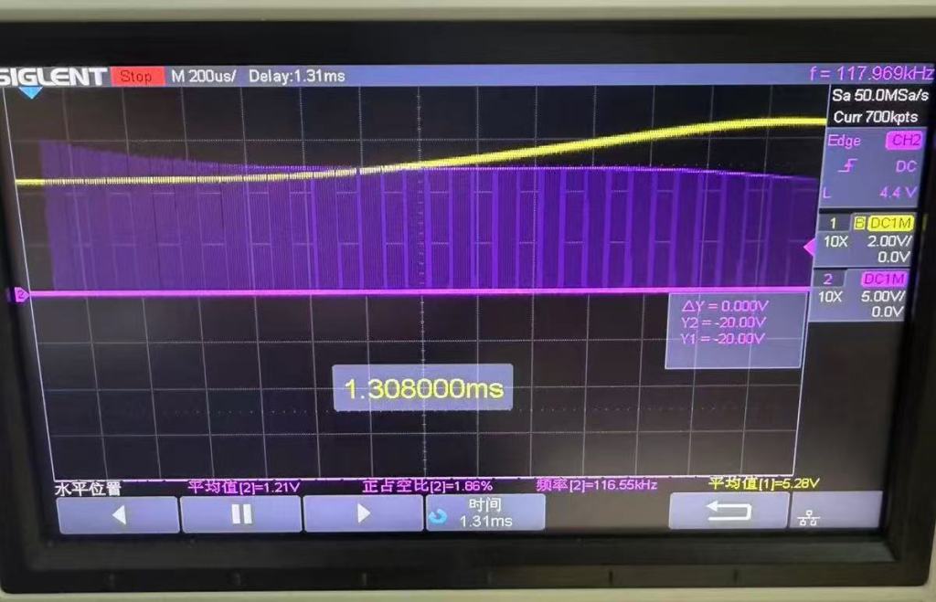
Vout (yellow) vs PWM (purple)

The measured waveforms confirm that as Vout overshoots 5 V, the PWM turns off, preventing further rise, and resumes switching once the voltage drops, achieving stable output regulation.
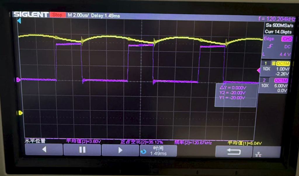
Vout (yellow) vs Feedback node (purple)
When Vout overshoots, the optocoupler conducts and raises the FB voltage. The comparator raises high which then shuts down the MOSFET, stablizing Vout to 5V.

Output with 10Ω Gold Aluminum Resistor Load: 5.04V
Average Output ripple: 14.54 mV

Reference
[1] Texas Instruments, UC1842, UC2842, UC3842, UC1843, UC2843, UC3843, UC1844, UC2844, UC3844, UC1845, UC2845, UC3845: Current-Mode PWM Controllers, datasheet, SLUS223H, Rev. Apr. 1997, Revised Oct. 2024. [Online]. Available: https://www.ti.com/lit/ds/symlink/uc3842.pdf
